You might notice that some of the answers are a bit outdated, but many others are very helpful:
RTSTM TW Frequently Asked QuestionsQuestions Oft' Asked and Answers Too!This page was composed from excerpts of the RTSTM "white book" and contains frequently asked questions and their answers. I would like to thank my colleagues for their assistance in compiling this section. These answers are not necessarily the only answers. For further information, please call the Burbank office at 818-566-6700. Sometimes, improvements in hardware or software will provide new options for you.
Q 1. How does my camera interface with the TW intercom? A 1. There are two problem areas in television camera intercoms:
Alternatives for Interfacing to Television Cameras:
An important point to note is that after an interface method is established, careful adjustment of the camera system electronics is often required to trade off signal to noise ratio, headroom, and level matching. Also, make sure the camera person has adequate sidetone in his headset but not an excessive or distorted amount. The sidetone should appear when the microphone is switched on. If an in-line microphone switch type headset cord is used, large transients may appear in the system, unless suppression is in place in the camera head intercom electronics. Q 2. How do I hook the up a TW intercom system to a telephone? A 2. There are several ways. Presently, the best interface on the market the "Link" produced by Telos. This interface has a digital signal processor that optimizes the matching of both telephone and TW line. Another way is to use a Triad S84X transformer and a toggle switch. This works well with a 802 or 803 master station and a phone line. Use a one to two step-up to the phone line (the TW line is 200 ohms and the phone is about 800 ohms). The transformer can withstand the DC from the phone line and can also be used to hold the phone line. The transformer cannot withstand the DC from the TW line and must be capacitor coupled to a TW line. Use 22 microfarad, 50 volt capacitors. Connect the negative side of each capacitor to one of the sides of the primary, hook the positive to the common and one channel of the TW system. Q 3. Is there an RTSTM wireless intercom? A 3. Yes, it is the Series 2100, and it is directly compatible with the TW system. Q 4. How do I hook the TW intercom system to a two-way radio? A 4. For a full duplex radio, a SSA324 can be used. For a simplex radio, where a transmitter key is required, a SSA324#U can be used. Any call light generated by a user station on the channel can key the SSA324#U. If a separate pair is used to key the radio, an ordinary SSA324 may be used. Additionally, some user stations provide drivers and relays for transmit keying. Q 5. What are the impedance parameters of the TW earpieces and headsets, in case I want to supply my own? A 5. Headset: Headphone: 25-1000 ohms. Mic: 150-500 ohms. Optimum performance is 200 ohms for the mic and 50 ohms for the headphone. Earpieces: 150 to 1000 ohms. Q 6. How do I tie two TW Intercom Systems together? A 6. Newer Equipment: Using (2) PS31 units, interconnect the audio outputs. It is recommended to use audio isolation transformers and safety capacitors, then set impedance switches on each PS31 to 400 ohms. Older Equipment: Connect as above. If one system has an impedance switch, use it. System level will drop 3 dB. If neither system has an impedance switch, the line level will drop 6 dB. Some older supplies can be modified to have impedance switches. Q 7. How do I create more intercom circuits using the TW System? A 7. By using the 200 ohm termination technique, you can create as many channels as you like. Contact 818-566-6700 for more details on this procedure. Q 8. How many 4001/VCP6 panels can I put into one system? A 8. 4001: Four (with priority), up to eight sharing priority. VCP6A: Three. VCP12B: Six (with the CIF612). Q 9. Why do I need so many power supplies in my system (WITH SOURCE ASSIGN PANEL) when there are only a few user stations? A 9. The RTSTM line format uses a 3 pin XLR connector (connected with microphone cable or 5 conductor cable). There are two communications channels riding on these three pins: one "wet" and one "dry." Channel one (wet), on pins 1 and 2 of the XLR, has "special" 32volts operating voltage on it as well as audio. An active impedance generator in the central power supply (PS15, etc) maintains the 200 Ohm operating impedance to permit audio transmission. To provide maximum source assignability of various communications circuits, a separate impedance generator is necessary for channel one source assignment. Channel two's source assignment is unaffected by the number of power supplies in a system, since external devices such as belt packs do not normally (i.e Phase III) derive their operating power from channel two. Q 10. Why do I have to use a TW power supply? A 10. If you want 2 channels on mic cable, it is a must! The TW Power Supply allows both audio signals, call light, and power to be on the same pair of wires. In the TW format, three wires, standard microphone cable, allow two channels of voice signals, two channels of call light signals and power. A regular, normal D.C. supply would act like a "short" at audio frequencies, and would provide operating power to the user stations, but would not pass audio on channel one. Q 11. How far can I run my lines? A 11. See Tables 12-1 and 12-2 below. Distance is based upon using 22 gage wire, and current at end of run. Note doubling the number of units at end of run will halve operating distance. Table 11-1 Maximum Operating Distances Vs. User Station Model #s (Using PS10, PS30,
PS31, PS50, or PS60)
Table 11-2 Maximum Operating Distances Vs User Station Model #s (Using PS8 Or PS15)
*Surface mount version. **Also valid for RMS300. ***Also valid for RMS300L. WM300, CM300 similar to BP300. WMS300 similar to SPK300. MRT327 similar to BP300 (headset operation), SPK300L (Speaker operation). Model BP350 is similar to the BP300, BP318 is similar to BP317. Q 12. How many units can I use with the PS31 power supplies? A 12. In both the PS15 and PS31 Technical Data Manuals, there is a nomograph that plots the number of speaker stations with and without call lights against the number of headset stations with and without call lights. It is best to use the nomograph, but the tables below will give a representation of how many like units that can be supported. An estimate may then be made of a mix based on your requirements. Table 12-1 PS31 Power Supply:
Note: Capacity can be increased by using two PS31 power supplies, splitting the load between the two supplies, interconnecting the supplies audio only, and by switching the power supply impedance switches from NORMAL to DUAL. Q 13. How many units can I use with the PS8 or PS15 power supplies? A 13. See table below. Table 13-1 PS15 or PS8 Power
Supply:
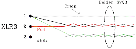
Note: Capacity can be increased by using two PS8/PS15 power supplies, splitting the load between the two supplies, interconnecting the supplies audio only, and by switching the power supply impedance switches from NORMal to DUAL. *Surface mount version. **Also valid for RMS300. ***Also valid for RMS300L. WM300, CM300 similar to BP300. WMS300 similar to SPK300. MRT327 similar to BP300 (headset operation), SPK300L (Speaker operation). Model BP350 is similar to the BP300, BP318 is similar to BP317. Q 14. What kind of cables should I use to hook up a TW System? A 14. Portable stations, use standard 3 Pin XLR microphone cable - but make sure that pin 1 is NOT connected to the connector shell!!! For fixed stations, use Belden two twisted pair cable. There are two kinds: type Belden 8723 and 9406. Type 9406 has a drain wire inside each shield, type 8723 has a single drain wire between the shields and the jacket. Another trade-off is the 9406 can have lower resistive crosstalk, but the 8723 has half the capacitance, which means given the same system frequency response, 8571 feet of 8723 can be used versus only 3175 feet of 9406. See typical interconnect diagram below using Belden 8723 cable.
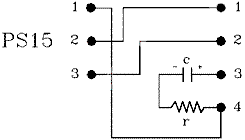
Q 15. How do I hook up a three channel system using a PS15? A 15. By using a special Switchcraft A3F to A4M adapter or a short interconnect cable using the same type connectors, wired as shown below.
c = 22 microfarad / 50 volt electrolytic capacitor r = 200 ohm 1/4 watt carbon film resistor. Q 16. How do I interface a TW intercom to Clear-Com ? A 16. An SSA324 System to System adapter may be used. Q 17. How do I adjust the cue/interrupt volume on a 4000 IFB System? A 17. Put a 220 ohm resistor across TB-1 (in the Models 4001,4002, or 4003) pins one & two. This will reduce the gain by 6 dB. Q 18. What's the difference between a PS30 & PS31? A 18. The PS30 has 3 wet and 3 dry audio channels. The wet channels were numbered 1,3,5; the dry, 2,4,6. The PS31 has 3 wet channels, plus the dual impedance switch. Upgraded circuitry design and reduction in channels reduces confusion on the part of the user when attaching the PS31 to a SAP1626. Q 19. How many Model 4000 Series IFB talent stations can I put on one line? A 19. A maximum of (3) three Model 4020s or 4030s may be attached to each output of a 4010 using a TW5W splitter or other means. Q 20. How do I increase the gain in the Model 465 Mic Preamp? A 20. Change R13 from 300 to 75 ohms. Increase of 10 dB gain. Q 21. How does the dual listen function operate? A 21. Dual Listen (DL) option uses concentric volume control knobs. RMS300/SPK300: Large knob is always Channel 1, small knob is always Channel 2. For all other user stations: Large knob is always the volume control for the channel you are talking on and the small knob is always the other channel. Q 22. I currently have an RMS300 and I want to add a 4001. How do I connect the two so I can use one gooseneck mic or headset for both? A 22. Use an RMS300 with the USMB option installed (see SD2712 in the RMS300 Technical Data Package, TDP3504). Modify the 4001 as detailed in the 4001 Service Manual in the sections entitled "Connection to existing microphones, "TW" type user stations and other sources" and in the figure entitled "Line Level Input". Use the USM OPTION on both the RMS300 and 4001. See the Series 4000 Technical Manual. Q 23. Why does the gooseneck not work when I turn off the speaker on the RMS300? A 23. The speaker ON/OFF switch shuts off both the speaker and panel microphone, the headsets are selected at this time. When the speaker ON/OFF switch is switched on, the speaker & gooseneck are selected, & the headsets are off. Q 24. When I turn up the volume on my RMS300 I get feedback on the speaker. How can I increase the gain without feedback? A 24. There are five ways:
Q 25. Is it okay to hook up a tape recorder to the line? If so, how do I do it? A 25. Yes, but not too many at one time. Select which channels you want to record and then use both an isolating audio transformer and blocking capacitors to couple the tape recorder into the circuit. Make certain the tape inputs are high impedance (10 kilohms or higher). Pins 1 & 2 = CH1 and pins 1 & 3 = CH2.
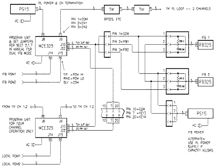
Typical channel 2 connection shown above. Capacitors C are 1 mf/50v electrolytic capacitors. The transformer is a 10,000 ohm to 10,000 ohm 100 mW minimum audio transformer. Q 26. I presently have one of the older TWI222/224 interfaces, and I want to put it on a rack. How hard is it to do? A 26. It's not difficult but it takes time. The front and back knobs, connectors and panels must come off the TWI222 or TWI224 and be remounted and rewired to the front rack mount front panel. Q 27. What is the relationship between the channels on the 802/803 master station, on the SAP1626, on the BOP220 and the channels on TW stations? A 27. Channels 1 to 12 on the 802 or 803 correspond to thumbwheel positions 1 to 12 on the SAP1626. Switch positions CH1 and CH2 on a user station correspond to the upper and lower rows of thumbwheels on the SAP1626. The 1-20 connectors on the BOP220 correspond to the vertical columns 1-20 of the "EXTERNAL" thumbwheels on the SAP1626 that create the circuit assignments. Q 28. How many master stations (Models 801, 802, 803, 8105CTL, 810CL, 848) can I put into a system? A 28. Up to 25 with 6 dB rolloff at 200 hertz, up to 50 with 6 dB rolloff at 400 hertz. This limitation does not apply to the unbalanced TW system, nor to the new Model 803. In general, a greater number of transformers in a system will cause low frequency loading. The model 802 master stations all have transformer balancing. Q 29. What is the difference between the 4000 Series IFB System and the IFB system on the 862? A 29. The 4000 Series is a complete IFB system. The 862 IFB feature is part of a system. To complete it, one must connect high impedance earphones, or for more level an amplifier and lower impedance phones. Another configuration using special wiring to integrate TW beltpacks or Model 4030 belt packs. The master station channels 7-12 may be selectively used for the IFB in this scenario. Q 30. Can I use old Phase I TW Intercom w/current TW? A 30. Not with a PS8 or PS15, but with certain other TW power supplies. The reason is that the Phase 1 intercom user station require power on both pins 2 and 3 with respect to pin 1 and the PS8 and PS15 only provides power on pin 2. Q 31. Is there an RTSTM wireless IFB system? A 31. Yes. It is a new series and consists of one TT-34 transmitter and TR-34 receiver per talent. Up to four of these may be used simultaneously. The IFB signal is generated upstream of the TT-34 transmitter via MCE325, 862, or 4000 series equipment. Q 32. How does the MCE325 perform the "local" IFB function? A 32. By internal programming, the MCE325 is first set to the 4 channel mode. Then, two jumpers are assigned so that up to two programs entering the MCE325 are distributed on channel 3 and 4. Two IFB-325, receive only, belt packs are attached through the PL native power supply. Legend buttons are changed on front panel to "IFB1", "IFB2". Keying circuits may be interconnected so that other MCE325 units can perform the IFB function, also. I will send to you a clear copy of the following drawing upon request:
Q 33. How are headsets wired to connect to the 4 and 5 pin female XLR's on the front panels? A 33. The pinouts are as follows:
Q 34. How do I bring a program source into a PL system when I am using a PS15 or PS8 power supply. A 34. The audio coupling jack on the back of either the PS15 or the PS8 serves as in injection point for external audio that may be superimposed onto the PL line. See diagram below:
Q 35. My MCE325 transmits okay, but doesn't receive. What's wrong? A 35. First, check to make sure that the unit is not set to the "four-channel mode". If it is, then you may have not changed the key caps to reflect the new setup. More likely, however, is the sidetone is not set correctly. A maladjusted sidetone control can completely or partially disable the receive signal to the unit. Set the sidetone to its null point to optimize the receiving capability of the unit, and to minimize local feedback. *** |


