Here's a page from Andrew McHaddad's website (www.plsystem.com):
RTS/Telex Equipment Pinouts |
|
|
|
|
|
|
|
| RTS BP-325 Line Connector | |||
| pin # | Use | Color |
|
| 1 | Common/GND | Shield | |
| 2 | Channel #1 audio and 30vdc | ||
| 3 | Channel #2 audio | ||
| verified-RTS BP-325 Loop/AUX Connector-PGM input mode | |||
| pin # | Use | Color | Uses the Rear Panel PGM Level control |
| 1 | Common/GND | Shield | |
| 2 | Non-inverting input | ||
| 3 | Inverting input | ||
| verified-RTS BP-325 Loop/AUX Connector-Local Power mode | |||
| pin # | Use | Color | |
| 1 | Common/GND | Shield | |
| 2 | 12-24VDC | ||
| 3 | NC | ||
| verified-RTS BP-325 STEREO Headset Connector | |||
| pin # | Use | Color | |
| 1 | mic signal low | Shield | |
| 2 | mic signal high | ||
| 3 | ear signal low | ||
| 4 | ear signal left | ||
| 5 | ear signal right | ||
| verified-RTS BP-325 MONO Headset Connector | |||
| pin # | Use | Color | |
| 1 | mic signal low | Shield | |
| 2 | mic signal high | ||
| 3 | ear signal low | ||
| 4 | ear signal high | ||
| verified-Telex KP98-7 4-pin Headset Connector | |||
| pin # | Use | Color | The HDST microphone input is balanced. To prevent headset cable MIC-EAR crosstalk, tie pin 1 to chassis ground. It is easiest to do this on the rear panel EXT HDSTconnector. |
| 1 | mic signal low | yel | |
| 2 | mic signal high | gry | |
| 3 | ear signal low | gry | |
| 4 | ear signal high | red | |
| Telex KP98-7 5-pin Headset Connector | |||
| pin # | Use | Color | Pin 4 and 5 are tied at the headset connector |
| 1 | mic signal low | yel | |
| 2 | mic signal high | gry | |
| 3 | ear signal low | gry | |
| 4 | ear signal high | red | |
| 5 | ear signal high | tie to pin 4 | |
| verified-Telex KP98-7 9-pin Rear-Panel Headset Connector (DB-9F) | |||
| pin # | Use | Color | Tie pin 2 to pin 6 to unbalance the dyn. mic input. |
| 1 | Dyn. mic + | ||
| 2 | Dyn. mic shield | ||
| 3 | Carbon mic +- | ||
| 4 | Carbon mic Shield | ||
| 5 | Ear signal high | ||
| 6 | Dyn. mic - | ||
| 7 | HDST SW control | ||
| 8 | HDST SW common | ||
| 9 | Ear signal common | ||
| 4010M or 828 IFB Power Supply Input Connector | |||
| pin # | Use | Color |
Low Numbered pin is Positive, High numbered pin is Negative. The chassis mount connector is Female |
| 1,26 | CH-1 N-INT | ||
| 2,27 | CH-1 INT | ||
| 3,28 | nc | ||
| 4,29 | CH-2 N-INT | ||
| 5,30 | CH-2 INT | ||
| 6,31 | nc | ||
| 7,32 | CH-3 N-INT | ||
| 8,33 | CH-3 INT | ||
| 9,34 | nc | ||
| 10,35 | CH-4 N-INT | ||
| 11,36 | CH-4 INT | ||
| 12,37 | nc | ||
| 13,38 | CH-5 N-INT | ||
| 14,39 | CH-5 INT | ||
| 15,40 | nc | ||
| 16,41 | CH-6 N-INT | ||
| 17,42 | CH-6 INT | ||
| 18,43 | nc | ||
| 19,44 | CH-7 N-INT | ||
| 20,45 | CH-7 INT | ||
| 21,46 | nc | ||
| 22,47 | CH-8 N-INT | ||
| 23,48 | CH-8 INT | ||
| 24,49 | nc | ||
| 25,50 | nc | Shield | |
| verified-Telex KP98-7, KP12, TIF951 Matrix Line Connector DB-9F | |||
| pin # | Use | Color |
  |
| 1 | DATA + | ||
| 2 | DATA - | ||
| 3 | GND, Shield Data | ||
| 4 | Station Output + (talk) | ||
| 5 | Station Output - (talk) | ||
| 6 | GND, Shield Audio | ||
| 7 | Station Input - (listen) | ||
| 8 | Station Input + (listen) | ||
| 9 | NC | ||
| verified-RTS 803/802 Front Panel Headset | |||
| pin # | Use | Color |
 |
| 1 | mic signal low | Shield | |
| 2 | mic signal high | ||
| 3 | ear signal low | ||
| 4 | ear signal left | ||
| 5 | ear signal right | ||
| RTS 803 DB-25 (J111) Connector | |||
| pin # | Use | Color |
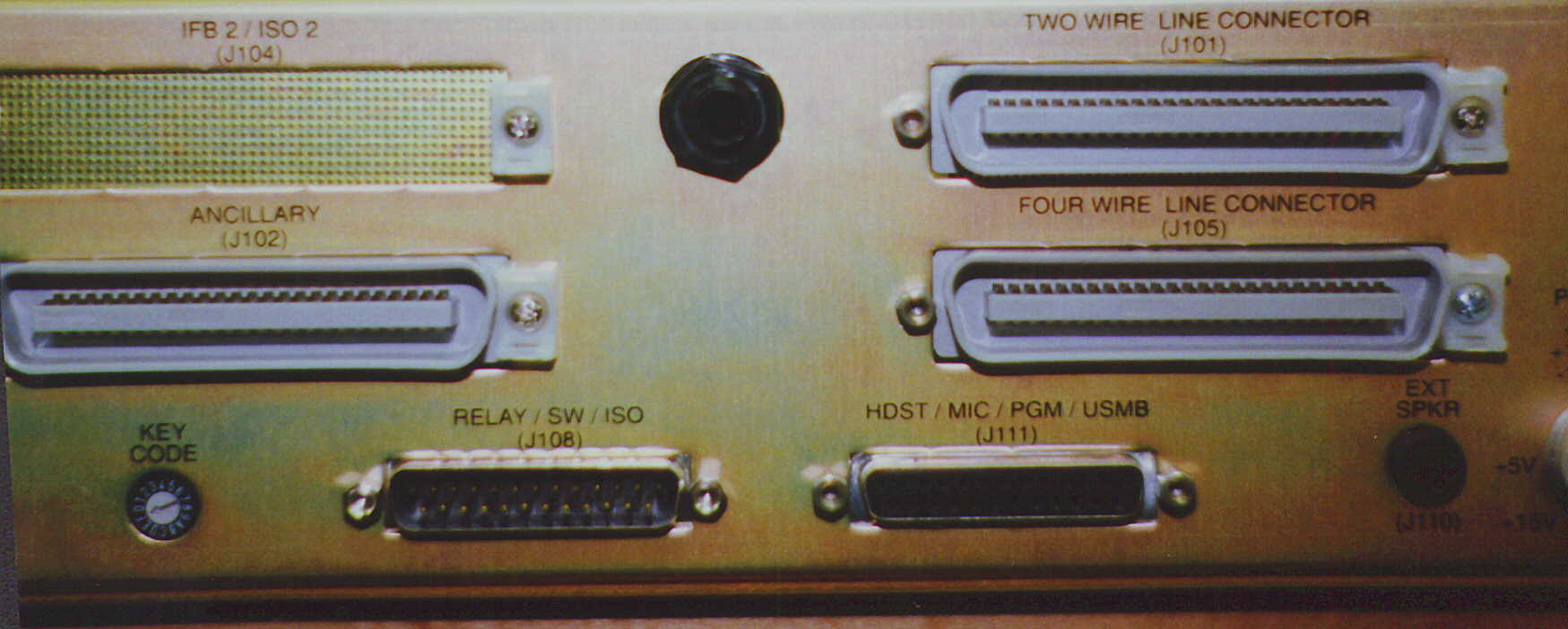 J111 is the female DB-25 connector on the right side of the lower part of the chassis. The USMB output is used to feed an RTS 4000 series IFB panel or it can be routed to a patchfield. |
| 1 | EXT HDST mic ground | ||
| 2 | EXT HDST Headphone gnd | ||
| 3 | EXT HDST Right Headphone high | ||
| 4 | Chassis ground | ||
| 5 | EXT Panel mic high | ||
| 6 | EXT carbon headset-common | ||
| 7 | EXT carbon headset-Headphone high | ||
| 8 | Digital ground | ||
| 9 | Program 1 high | ||
| 10 | Program 2 high | ||
| 11 | Chassis ground | ||
| 12 | Unswitched mic out high | ||
| 13 | Chassis ground | ||
| 14 | EXT HDST mic high | ||
| 15 | EXT HDST Left headphone high | ||
| 16 | Chassis ground | ||
| 17 | EXT Panel mic low | ||
| 18 | EXT Panel mic excitation | ||
| 19 | EXT carbon headset-mic high | ||
| 20 | NC | ||
| 21 | Program 1 low | ||
| 22 | Program 2 low | ||
| 23 | Chassis ground | ||
| 24 | Unswitched mic out low | ||
| 25 | Chassis ground | ||
| RTS 803 DB-25 (J108) Connector | |||
| pin # | Use | Color | Male DB-25 connector. Notes |
| 1 | Relay 1 N.O. | ||
| 2 | Relay 1 N.C. | ||
| 3 | Relay 2 COM | ||
| 4 | Relay 3 N.O. | ||
| 5 | Relay 3 N.C. | ||
| 6 | Relay 4 COM | ||
| 7 | Relay 5 N.O. | ||
| 8 | Relay 5 N.C. | ||
| 9 | Relay 6 COM | ||
| 10 | XSW & YSW Common | ||
| 11 | EXT Switch YSW N.O. | ||
| 12 | EXT. ISO Control input N.O. | ||
| 13 | Bilat 15 Audio High | ||
| 14 | Relay 1 COM | ||
| 15 | Relay 2 N.O. | ||
| 16 | Relay 2 N.C. | ||
| 17 | Relay 3 COM | ||
| 18 | Relay 4 N.O. | ||
| 19 | Relay 4 N.C. | ||
| 20 | Relay 5 COM | ||
| 21 | Relay 6 N.O. | ||
| 22 | Relay 6 N.C. | ||
| 23 | EXT Switch XSW N.O | ||
| 24 | EXT. ISO Control input Common | ||
| 25 | Bilat 15 Audio Low | ||
| RTS SAP-1626 Camera Connector DB-25F | |||
| pin # | Use | Color | FEMALE DB-25 |
| 1 | common | ||
| 2 | common | ||
| 3 | common | ||
| 4 | common | ||
| 5 | common | ||
| 6 | common | ||
| 7 | common | ||
| 8 | common | ||
| 9 | common | ||
| 10 | common | ||
| 11 | common | ||
| 12 | common | ||
| 13 | NC | ||
| 14 | Camera 1 CH-1 | ||
| 15 | Camera 2 CH-1 | ||
| 16 | Camera 3 CH-1 | ||
| 17 | Camera 4 CH-1 | ||
| 18 | Camera 5 CH-1 | ||
| 19 | Camera 6 CH-1 | ||
| 20 | Camera 1 CH-2 | ||
| 21 | Camera 2 CH-2 | ||
| 22 | Camera 3 CH-2 | ||
| 23 | Camera 4 CH-2 | ||
| 24 | Camera 5 CH-2 | ||
| 25 | Camera 6 CH-2 | ||
| RTS SSA-324 System/System Interface Four Wire Connector J103 DB-25F | |||
| pin # | Use | Color | The audio I/O on this connector are also duplicated on the TB-1 terminal block. |
| 1 | earth | ||
| 2 | 4-Wire Audio In Hi, System A | ||
| 3 | 4-Wire Audio Out Hi, System A | ||
| 4 | 4-Wire Audio In Hi, System B | ||
| 5 | 4-Wire Audio Out Hi, System B | ||
| 6 | Call Signal Ground (A) | ||
| 7 | DC Call Sig En GND (A) | ||
| 8 | Relay Contact NO (A) | ||
| 9 | Relay Contact COM (A) | ||
| 10 | RelayRelay NC (B) | ||
| 11 | Call Send GND (B) | ||
| 12 | DC Call Sig En GND (B) | ||
| 13 | NC | ||
| 14 | NC | ||
| 15 | 4-Wire Audio In Lo, System A | ||
| 16 | 4-Wire Audio Out Lo, System A | ||
| 17 | 4-Wire Audio In Lo, SystemB | ||
| 18 | 4-Wire Audio Out Lo, System B | ||
| 19 | Call Send Hi (A) | ||
| 20 | DC Call Sig En Hi (A) | ||
| 21 | Relay Contact NC (A) | ||
| 22 | Relay Contact NO (B) | ||
| 23 | Relay Contact COM (B) | ||
| 24 | Call Send Hi (B) | ||
| 25 | DC Call Sig En Hi (B) | ||
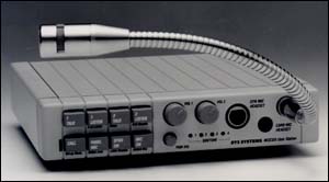
| RTS MCE-325 FP Headset Connector | |||
| pin # | Use | Color |
 For remote Mic on/off: short pin-1 to pin-6 to turn on the microphone. |
| 1 | HDST Mic LO (-) | ||
| 2 | HDST Mic HI Com. | ||
| 3 | Ear Common (LO) | ||
| 4 | Ear Left HI | ||
| 5 | Ear Right HI | ||
| 6 | Remote Mic On/Off | ||
| RTS MCE-325 DB-25 Accessory Connector DB-25F | |||
| pin # | Use | Color | This female DB-25 connector has it all. The USMB output is used to feed an RTS 4000 series IFB panel mic signal in. On the 4001 IFB panel, use TB-2 pins 3 and 4 for line level input. |
| 1 | USMB -Hot Mic Out LO (-) | ||
| 2 | EXT Panel Mic Com. | ||
| 3 | Chassis Ground | ||
| 4 | HDST Mic HI | ||
| 5 | HDST Ear HI Left | ||
| 6 | Talk Key #1 Logic Out | ||
| 7 | Talk Key #3 Logic Out | ||
| 8 | 4W-A HI | ||
| 9 | 4W-B HI | ||
| 10 | Common | ||
| 11 | Common | ||
| 12 | ISO Logic | ||
| 13 | Ext +14 VDC in | ||
| 14 | USMB -Hot Mic Out HI (+) | ||
| 15 | EXT Panel Mic HI | ||
| 16 | HDST Mic HI | ||
| 17 | HDST Ear Common (LO) | ||
| 18 | HDST Ear HI Right | ||
| 19 | Talk Key #2 Logic Out | ||
| 20 | Talk Key #4 Logic Out | ||
| 21 | 4W-A LO | ||
| 22 | 4W-B LO | ||
| 23 | Ext +18 VDC in | ||
| 24 | Rem. Mic ON logic in | ||
| 25 | Speaker mute logic in. | ||
| RTS MCE-325 External Speaker | |||
| pin # | Use | Color |
NOTE: DO NOT USE a Metal Shell Connector. This is a balanced speaker driver. Shorting either tip or ring to ground will result in a call to the Telex Service department. |
| Tip | Speaker amp + out | ||
| Ring | Speaker amp - out | ||
| Sleeve | No connection. | ||
| 4030 IFB Beltpack | |||
| pin # | Use | Color |
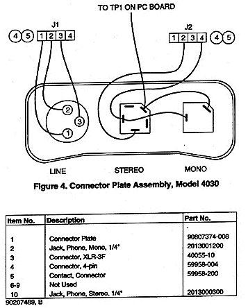 |
| Line Conector | |||
| 1 | Line Commont | ||
| 2 | Channel 1 | ||
| 3 | Channel 2 | ||
| Stereo Earpiece | |||
| Tip | Interrupt | ||
| Ring | Non-Interrupt | ||
| Sleve | Ground | ||
| Mono Earpiece | |||
| Tip | Interrupt | ||
| Sleve | Ground | ||
| verified-Telex KP-32 Relay 1&2(DB-9M) | |||
| pin # | Use | Color | |
| 1 | N.C. Contact K1 | ||
| 2 | Common K1 | ||
| 3 | N.O. Contact K1 | ||
| 4 | N.C. Contact K2 | ||
| 5 | Common K2 | ||
| 6 | N.O. Contact 2 | ||
| 7 | +5V DC | ||
| 8 | Ground | ||
| 9 | +5V DC | ||
| verified-Telex KP-32 Relay 3&4(DB-9M) | |||
| pin # | Use | Color | |
| 1 | N.C. Contact K3 | ||
| 2 | Common K3 | ||
| 3 | N.O. Contact K3 | ||
| 4 | N.C. Contact K4 | ||
| 5 | Common K4 | ||
| 6 | N.O. Contact 4 | ||
| 7 | +5V DC | ||
| 8 | Ground | ||
| 9 | +5V DC | ||
| verified-Telex KP-32 Opto 1-4 Input(DB-9M) | |||
| pin # | Use | Color | Tie any switch input to ground to activate that input (pin 1-4) |
| 1 | Input 1 GND | ||
| 2 | Input 2 GND | ||
| 3 | Input 3 GND | ||
| 4 | Input 4 GND | ||
| 5 | GND | ||
| 6 | Switch Contact Input 1 | ||
| 7 | Switch Contact Input 1 | ||
| 8 | Switch Contact Input 1 | ||
| 9 | Switch Contact Input 1 | ||
| verified-Telex KP-32 OC 1 & 2(DB-9M) | |||
| pin # | Use | Color | . |
| 1 | GND OC1 | ||
| 2 | Emitter OC1 | ||
| 3 | Collector OC1 | ||
| 4 | GND OC2 | ||
| 5 | Emitter OC2 | ||
| 6 | Collector OC2 | ||
| 7 | +5V DC | ||
| 8 | NC | ||
| 9 | +5V DC | ||
| verified-Telex KP-32 Rear-Panel Headset Connector (DB-9M) | |||
| pin # | Use | Color | Tie pin 1 to pin 9 to unbalance the dyn. mic input. |
| 1 | GND | ||
| 2 | nc | ||
| 3 | nc | ||
| 4 | nc | ||
| 5 | Balanced Dynamic Mic Input + | ||
| 6 | GND | ||
| 7 | Headset Listen Out Left | ||
| 8 | Headset Listen Out Right | ||
| 9 | Balanced Dynamic Mic Input - | ||
| verified-Telex KP-32 Footswitch /Speaker DB-9M | |||
| pin # | Use | Color | . |
| 1 | GND | ||
| 2 | Speaker (-) | ||
| 3 | GND | ||
| 4 | nc | ||
| 5 | Foot Switch | ||
| 6 | Speaker (+) | ||
| 7 | nc | ||
| 8 | nc | ||
| 9 | GND | ||
| verified-Telex KP-32 External Microphone Input XLR-3F | |||
| pin # | Use | Color | . |
| 1 | Shield | ||
| 2 | DC Bias and Audio (+) | ||
| 3 | GND | ||
| verified-Telex KP-32 Balanced Microphone Output XLR-3M | |||
| pin # | Use | Color | . |
| 1 | Shield | ||
| 2 | Audio (+) | ||
| 3 | Audio (-) | ||
© Copyright 2002 - Technical Audio Solutions